The display list interrupt (DLI) is one of the most powerful capabilities built into the ATARI Home Computer. It is also one of the least accessible features of the system, requiring a firm understanding of assembly language as well as all of the other characteristics of the machine. Display list interrupts all by themselves provide no additional capabilities; they must be used in conjunction with the other features of the system such as player-missile graphics, character set indirection, or color register indirection. With display list interrupts the full power of these features can be deployed.
Display list interrupts take advantage of the sequential nature of the raster scan television display. The television draws the screen image in a time sequence. It draws images from the top of the screen to the bottom. This drawing process takes about 17,000 microseconds, which looks instantaneous to the human eye, but is a long time in the time scale that the computer works in. The computer has plenty of time to change the parameters of the screen display while it is being drawn. Of course, it must effect each change each time the screen is drawn, which is 60 times per second. Also (and this is the tricky part), it must change the parameter in question at exactly the same time each time the screen is drawn. That is, the cycle of changing screen parameters must be synchronized to the screen drawing cycle. One way to do this might be to lock the 6502 up into a tight timing loop whose execution frequency is exactly 60 Hertz. This would make it very difficult to carry out any computations other than the screen display computations. It would also be a tedious job. A much better way would be to interrupt the 6502 just before the time has come to change the screen parameters. The 6502 responds to the interrupt, changes the screen parameters, and returns to its normal business. The interrupt to do this must be precisely timed to occur at exactly the same time during the screen drawing process. This specially timed interrupt is provided by the ANTIC chip; it is called a display list interrupt (DLI).
The timing and execution of any interrupt process can be intricate; therefore we will first narrate the sequence of events in a properly working DLI. The process begins when the ANTIC chip encounters a display list instruction with its interrupt bit (bit D7) set. ANTIC waits until the last scan line of the mode line it is currently displaying. ANTIC then refers to its NMIEN register to see if display list interrupts have been enabled. If the enable bit is clear, ANTIC ignores the interrupt and continues its regular tasks. If the enable bit is set, ANTIC pulls down the NMI line on the 6502. ANTIC then goes back to its normal display activities. The 6502 vectors through the NMI vector to an interrupt service routine in the OS. This routine first determines the cause of the interrupt. If the interrupt is indeed a DLI, the routine vectors through addresses $0200, $0201 (low then high) to a DLI service routine. The DLI routine changes one or more of the graphics registers which control the display. Then the 6502 RTIs to resume its mainline program.
There are a number of steps involved in setting up a DLI. The very first thing you must do is write the DLI routine itself. The routine must push any 6502 registers that will be altered onto the stack, as the OS interrupt poll routine saves no registers. (The 6502 does automatically push the Processor Status Register onto the stack.) The routine should be short and fast; it should only change registers related to the display. It should end by restoring any 6502 registers pushed onto the stack. Next you must place the DLI service routine somewhere in memory. Page 6 is an ideal place. Set the vector at $0200, $0201 to point to your routine. Determine the vertical point on the screen where you want the DLI to occur, then go to the corresponding display list instruction and set bit D7 of the previous instruction. Finally, enable the DLI by setting bit D7 of the NMIEN register at $D40E. The DLI will immediately begin functioning.
DLI TIMING
As with any interrupt service routine, timing considerations can be critical. ANTIC does not send the interrupt to the 6502 immediately upon encountering an interrupt instruction; it delays this until the last scan line of the interrupting mode line. There are a number of processing delays before the DLI reaches your service routine. Thus, your DLI service routine will begin executing while the electron beam is partway across the screen in the last scan line of the interrupting mode line. For example, if such a DLI routine changes a color register, the old color will be displayed on the left half of the screen and the new color will show up on the right half of the screen. Because of uncertain timing in the response of the 6502 to an interrupt, the border between them will not be sharp but will jiggle back and forth irritatingly.
There is a solution to this problem. It is provided in the form of the WSYNC (wait for horizontal sync) register. Whenever this register is addressed in any way, the ANTIC chip pulls down the ROY line on the 6502. This effectively freezes the 6502 until the register is reset by a horizontal sync. The effect is that the 6502 freezes until the electron beam reaches the right edge of the standard playfield. If you insert a STA WSYNC instruction just before the instruction which stores a value into a color register, the color will go into the color register while the beam is off the screen. The color transition will occur one scan line lower, but will be neat and clean.
The proper use of a DLI then is to set the DLI bit on the mode line before the mode line for which you want the action to occur. The DLI service routine should first save the 6502 registers onto the stack, and then load the 6502 registers with the new graphics values to be used. It should execute a STA WSYNC, and then store the new values into the appropriate ANTIC or CTIA registers. Finally, it should restore the 6502 registers and return from the interrupt. This procedure will guarantee that the graphics registers are changed at the beginning of the desired line while the electron beam is off the screen.
DLI EXAMPLE
A simple program demonstrating a DLI is given below:
|
10 DLIST=PEEK(560)+256*PEEK(561):REM Find display list |
This routine uses the following assembly language DLI service routine:
|
PHA Save accumulator |
This is a very simple DLI routine. It changes the background color from blue to pink. It also changes the color of the characters so that they show up as dark against the pink background. You might wonder why the upper half of the screen remains blue even though the DLI routine keeps stuffing pink into the color register. The answer is that the OS vertical blank interrupt routine keeps stuffing blue into the color register during the vertical blank period. The blue color comes from the OS shadow register for that color register. Every hardware color register is shadowed out to a RAM location. You may already know about these shadow registers at locations 708 through 712. For most purposes you can change colors by poking values into the shadow registers. If you poke directly into the hardware registers, the OS shadow process will wipe out your poked color within a 60th of a second. For DLls, however, you must store your new color values directly into the hardware registers. You can not use a DLI to set the color of the first displayed line of the screen; the OS takes care of that line for you. Use DLls to change colors of lines below the first line.
ATTRACT MODE
By stuffing colors directly into the hardware registers, you create a new problem: you defeat the automatic attract mode. Attract mode is a feature provided by the operating system. After nine minutes without a keypress, the colors on the screen begin to cycle through random hues at lowered luminances. This ensures that a computer left unattended for several hours does not burn an image into the television screen. 1t is easy to build attract mode into a display list interrupt. Only two lines of assembly code need be inserted into the DLI routine:
|
Old |
New |
|
LDA NEWCOL |
LDA NEWCOL |
|
STA WSYNC |
EOR COLRSH |
|
STA COLPF2 |
AND DRKMSK |
|
|
STA WSYNC |
|
STA COLPF2 |
DRKMSK and COLRSH are zero page locations ($4E and $4F) set up and updated by the OS during vertical blank interrupt. When attract mode is not in force, COLRSH takes a value of 00 and DRKMSK takes $FF. When attract mode is in force, COLRSH is given a new random value every 4 seconds and DRKMSK holds a value of $F6. Thus, COLRSH scrambles the color and DRKMSK lops off the highest luminance bit.
DETAILED TIMING CONSIDERATIONS
The implementation of attract mode in DLls exacerbates an already difficult problem: the shortage of execution time during a DLI. A description of DLI timing will make the problem more obvious. DLI execution is broken into three phases: - Phase One covers the period from the beginning of the DLI to the STA WSYNC instruction. During Phase One the electron beam is drawing the last scan line of the interrupting mode line. - Phase Two covers the period from the STA WSYNC instruction to the appearance of the beam on the television screen. Phase Two corresponds to horizontal blank; all graphics changes should be made during Phase Two. - Phase Three covers the period from the appearance of the beam on the screen to the end of the DLI service routine. The timing of Phase Three is not critical.
One horizontal scan line takes 114 processor clock cycles of real time. A DLI reaches the 6502 on cycle number 8. The 6502 takes from 8 to 14 cycles to respond to the interrupt. The OS routine to service the interrupt and vector it on to the DLI service routine takes 11 machine cycles. During this time from 1 to 3 cycles wi11 be stolen for memory refresh DMA. Thus, the DLI service routine is not reached until from 28 to 36 clock cycles have elapsed. For planning purposes we must assume the worst case and program as if the DLI service routine is reached on cycle number 36. Furthermore, the
STA WSYNC instruction must be reached by cycle number 100; this reduces the time available in Phase One by 14 cycles. Finally, ANTIC's DMA will steal some of the remaining clock cycles from the 6502. Nine cycles will be lost to memory refresh DMA. This leaves an absolute maximum of 55 cycles available for Phase One. This maximum is achieved only with blank line mode lines. Character and map mode instructions will result in the loss of one cycle for each byte of display data. The worst case arises with BASIC modes 0, 7, and 8, which require 40 bytes per line. Only 15 machine cycles are available to Phase One in such modes. Thus, a Phase One routine will have from 15 to 55 machine cycles of execution time available to it.
Phase Two, the critical phase, extends over 27 clock cycles of real time. As with Phase One, some of these cycles are lost to cycle stealing DMA. Player-missile graphics will cost five cycles if they are used. The display instruction will cost one cycle; if the LMS option is used, two more cycles will be stolen. Finally, one or two cycles may be lost to memory refresh or display data retrieval. Thus, from 17 to 26 machine cycles are available to Phase Two.
The problems of DLI timing now become obvious. To load, attract and store a single color will consume 14 cycles. Saving A, X, and Y onto the stack and then loading, attracting, and saving three colors into A, X, and Y will cost 47 cycles, most if not all of Phase One. Obviously, the programmer who wishes to use DLI for extensive graphics changes will expend much effort on the timing of the DLI. Fortunately, the beginning programmer need not be concerned with extensive timing calculations. If only single color changes or simple graphics operations are to be performed, cycle counting and speed optimization are unnecessary. These considerations are only important for high-performance situations.
There are no simple options for the programmer who needs to change more than three color registers in a single DLI. It might be possible to load, attract, and store a fourth color early in Phase Three if that color is not displayed on the left edge of the screen. Similarly, a color not showing up on the right side of the screen could be changed during Phase One. Another approach is to break one overactive DLI into two less ambitious DLls, each doing half the work of the original. The second DLI could be provided by inserting a single scan line blank instruction (with DLI bit set) into the display list just below the main interrupting mode line. This will consume some screen space.
Another partial solution is to perform the attract chores during vertical blank periods. To do this, two tables of colors must be kept in RAM. The first table contains color values intended to be displayed by the DLI routines. The second table contains the attracted values of these colors. During vertical blank, a user-supplied interrupt service routine fetches each color from the first table, attracts it, and stores the attracted color to the second table. The DLI routine then retrieves values directly from the second table without paying the time penalty for attract.
MULTIPLE DLls
It is often desirable to have a number of DLls occurring at several vertical positions on the screen. This is an important way to add color to a display. Unfortunately, there is only one DLI vector; if multiple DLls are to be implemented then the vectoring to the appropriate DLI must be implemented, in the DLI routine itself. There are several ways to do this. If the DLI routine does the same process with different values then it can be table-driven. On each pass through the DLI routine, a counter is incremented and used as an index to a table of values. A sample DLI routine for doing this is as follows:
|
PHA |
The BASIC program to call this routine is:
|
10 GRAPHICS 7 |
This program will put 80 different colors onto the screen.
There are other ways to implement multiple DLls. One way is to use a DLI counter as a test for branching through the DLI service routines to the proper DLI service routine. This slows down the response of all the DLls, particularly the ones at the end of the test sequence. A better way is to have each DLI service routine write the address of the next routine into the DLI vector at $200, $201. This should be done during Phase Three. This is the most general solution to the problem of multiple DLls. It has the additional advantage that vectoring logic is performed after the time critical portion of the DLI, not before.
The OS keyboard click routine interferes with the function of the DLI. Whenever a key is pressed and acknowledged, the onboard speaker is clicked. The timing for this click is provided by several STA WSYNC instructions. This can throw off the timing of a DLI routine and cause the screen colors to jump downward by one scan line for a fraction of a second. There is no easy solution to this problem. One possible solution involves the VCOUNT register, a read-only register in ANTIC which tells what scan line ANTIC is displaying. A DLI routine could examine this register to decide when to change a color. Another solution is to disable the OS keyboard service routine and provide your own keyboard routine. This would be a tedious job. The final solution is to accept no inputs from the keyboard. If key presses are-not acknowledged, the screen jiggle does not occur.
KERNELS
The DLI was designed to replace a more primitive software/hardware technique called a kernel. A kernel is a 6502 program loop which is precisely timed to the display cycle of the television set. By monitoring the VCOUNT register and consulting a table of screen changes catalogued as a function of VCOUNT values, the 6502 can arbitrarily control all graphics values for the entire screen. A high price is paid for this power: the 6502 is not available for computations during the screen display time, which is about 75 percent of the time. Furthermore, no computation may consume more than the 4000 or so machine cycles available during vertical blank and overscan periods. This restriction means that kernels can only be used with programs requiring little computation, such as certain skill and action games. For example, the BASKETBALL program for the ATARI 400/800 Computers uses a kernel; the program requires little computation but much color. The multicolored players in this game could not be done with display list interrupts, because DLls are keyed to playfield vertical positions, not player positions.
It is possible to extend the kernel idea right into a single scan line and change graphics registers on the fly. In this way a single color register can present several colors on a single scan line. The horizontal position of the color change is determined by the amount of time that elapses before the change goes in. Thus, by carefully counting machine cycles, the programmer can get more graphics onto the screen. Unfortunately, this is extremely difficult to achieve in practice. With ANTIC DMAing the 6502, it is very difficult to know exactly how many cycles have really elapsed; a simple count of 6502 cycles is not adequate. If ANTIC's DMA Is turned off, the 6502 can assume full control of the display but must then perform all the work that ANTIC normally does. For these reasons horizontal kernels are seldom worth the effort. However, if the two images to be displayed in different colors are widely separated, say by 20 color clocks or more, the separation should cover up the timing uncertainties and render this technique feasible.
APPLICATIONS OF DISPLAY LIST INTERRUPTS
The tremendous value of graphics indirection and all those modifiable registers in the hardware now becomes obvious. With display list interrupts, every one of those registers can be changed on the fly. You can put lots of color, graphics, and special effects onto the screen. The most obvious application of DLls is to put more color onto the screen. Each color register can be changed as many times as you have DLls. This applies to both playfield color registers and player color registers. Thus, you have up to nine color registers, each of which can display up to 128 different colors. Is that enough color for you? Of course, a normal program would not lend itself to effectively using all of those colors. Too many DLls start slowing down the whole program. Sometimes the screen layout cannot accommodate lots of DLls. In practice, a dozen colors is easy, two dozen requires careful planning, and more than that requires a contrived situation.
Display list interrupts can give more than color; they can also be used to extend the power of player-missile graphics. The horizontal position of a player can be changed by a DLI. In this way a player can be repositioned partway down the screen. A single player can have several incarnations on the screen. If you imagine a player as a vertical column with images drawn on it, a DLI becomes a pair of scissors with which you can snip the column and reposition sections of it on the screen. Of course, no two sections of the player can be on the same horizontal line, so two incarnations of the player cannot be on the same horizontal line. If your display needs allow graphics objects that will never be on the same horizontal line, a single player can do the job.
Another way to use DLls in conjunction with players is to change their width or priority. This would most often be used along with the priority masking trick described in Section 4.
The last application of DLls is the changing of character sets partway down the screen. This allows a program to use character graphics in a large window and regular text in a text window. Multiple character set changes are possible; a program might use one graphics character set at the top of the screen, another graphics character set in the middle of the screen, and a regular text character set at the bottom. A `Rosetta Stone' program would also be possible, showing different text fonts on the same screen. The vertical reflect bit can be changed with a DLI routine, allowing some text to be rightside up and other text to be upside down.
The proper use of the DLI requires careful layout of the screen display. The designer must give close consideration to the vertical architecture of display. The raster scan television system is not two-dimensionally symmetric; it has far more vertical structure than horizontal structure. This is because the pace for horizontal screen drawing is 262 times faster than the pace for vertical screen drawing. The ATARI Home Computer display system was designed specifically for raster scan television, and it mirrors the anisotropy of the raster scan system. The ATARI Home Computer display is not a flat, blank sheet of paper on which you draw; it is a stack of thin strips, each of which can take different parameters. The programmer who insists on designing an isotropic display wastes many opportunities. You will achieve optimal results when you organize the information you wish to display in a strong vertical structure. This allows the full power of the DLI to be brought to bear.
Figure 5-1 shows some screen displays from various programs and gives estimates of the degree of vertical screen architecture used in each.
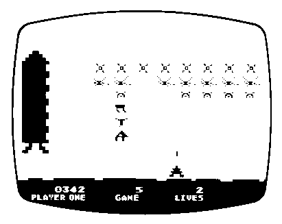
SPACE INVADERS
(Trademark of Taito America Corporation)
***LOTS***
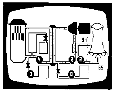
SCRAM
(A Nuclear Reactor Simulation)
***LITTLE***
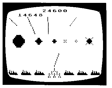
MISSILE COMMAND
***SOME***
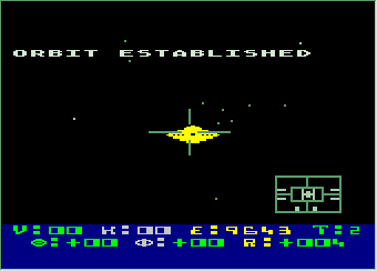
STAR RAIDERS
***LITTLE***
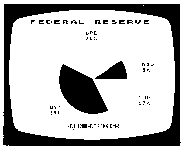
GRAPH IT
***NONE***
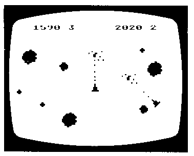
ASTEROIDS
***NONE***
Figure 5-1 Examples of Vertical Screen Architecture
